画像をクリックすると拡大表示できます。
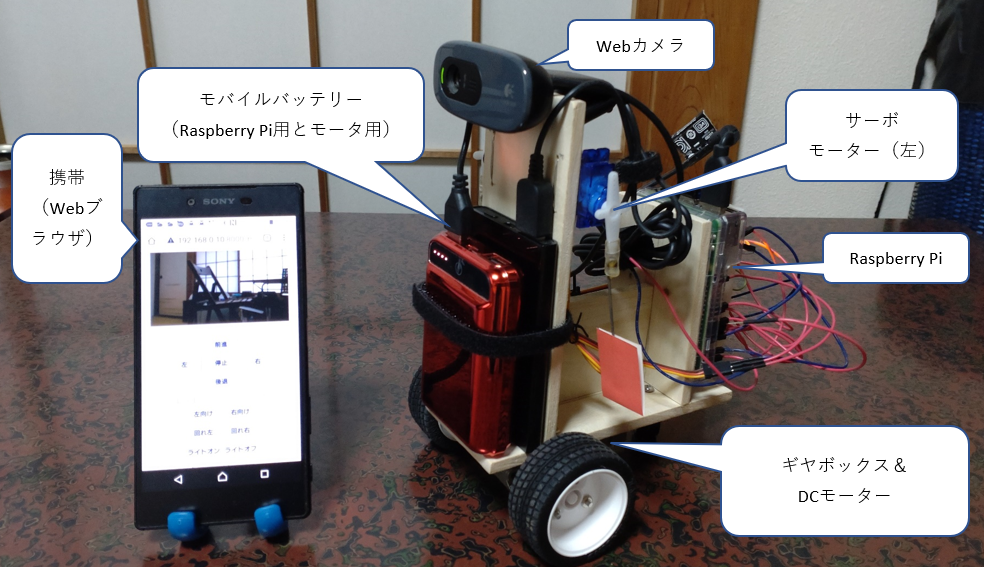
ここでは、簡単なロボットを作って、LEDランプのON/OFF、DCモータの制御、サーボモータの制御、Webカメラのストリーミング配信の基本機能を試して見ます。
また、Webとの連携ソフトを使ってスマートフォンで操作出来るようにします。
Webiopiインストールしていない場合は「Webブラウザからの遠隔制御(Webiopi)の設定」でインストールして下さい。
設定デイレクトリーは下記の通りとします。
ユーザディレクトリ/xxx
          ┣ script.py(pythonプログラムの処理)
          ┗ zzzz.html (HTMLプログラム)
個別プログラムと連動する場合は、Webiopi開始時のPythonスクリプトとHTMLドキュメントのディレクトリ及び
省略時のHTMLファイル名を「/etc/webiopi/config」ファイルに追記して指定します。
・・・・省略・・・・
[SCRIPTS]
# Load custom scripts syntax :
# name = sourcefile
# each sourcefile may have setup, loop and destroy functions and macros
#myscript = /home/pi/webiopi/examples/scripts/macros/script.py
myscript = /home/pi/xxx/script.py
#------------------------------------------------------------------------#
[HTTP]
# HTTP Server configuration
enabled = true
port = 8000
# File containing sha256(base64("user:password"))
# Use webiopi-passwd command to generate it
passwd-file = /etc/webiopi/passwd
# Change login prompt message
prompt = "WebIOPi"
# Use doc-root to change default HTML and resource files location
#doc-root = /home/pi/webiopi/examples/scripts/macros
doc-root = /home/pi/xxx
# Use welcome-file to change the default "Welcome" file
#welcome-file = index.html
welcome-file = zzzz.html
#------------------------------------------------------------------------#
・・・・省略・・・・
import webiopi
###################################################
# LED制御
###################################################
webiopi.setDebug()
GPIO = webiopi.GPIO
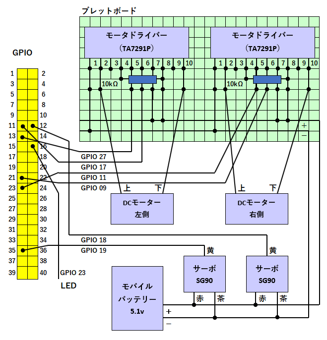
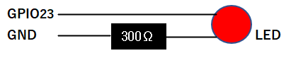
LIGHT = 23 # GPIO pin using BCM numbering
GPIO.setFunction(LIGHT, GPIO.OUT)
GPIO.digitalWrite(LIGHT, GPIO.HIGH)
@webiopi.macro
def lighton():
GPIO.digitalWrite(LIGHT, GPIO.HIGH)
@webiopi.macro
def lightoff():
GPIO.digitalWrite(LIGHT, GPIO.LOW)
# destroy function is called at WebIOPi shutdown
def destroy():
GPIO.digitalWrite(LIGHT, GPIO.LOW)
<!DOCTYPE html>
<html lang="ja">
<head>
<meta charset="UTF-8">
<title>RaspberryPi</title>
<meta name="viewport" content="width=device-width,initial-scale=1">
<script type="text/javascript" src="/webiopi.js"></script>
</head>
<body>
<H1 style="text-align:center;">RaspberryPi</H1>
<form name="form">
<table style="margin:0 auto;"><tr><td style="text-align:center;">
<input class="bt" type="button" value="ライトオン" onclick="webiopi().callMacro( 'lighton' );"></td><td>
<input class="bt" type="button" value="ライトオフ" onclick="webiopi().callMacro( 'lightoff' );"></td></tr>
</table>
</form>
<script>
webiopi().ready( initialize_webiopi );
function initialize_webiopi(){
    // GPIOの状態を監視しない
    webiopi().refreshGPIO(false);
}
</script>
</body>
</html>
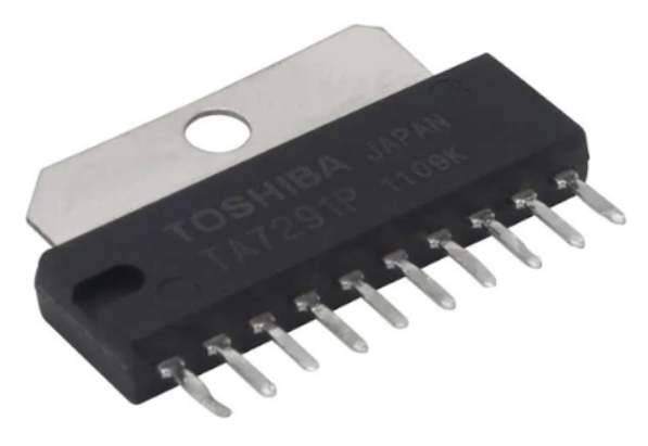
| PIN 端子 |
名称 | 機能 |
| 1 | GND | GND |
| 2 | OUT1 | モーター出力端子1 |
| 3 | NC | 未接続 |
| 4 | VREF | 制御電源端子(0〜20V)※ |
| 5 | IN1 | ロジック入力端子1 |
| 6 | IN2 | ロジック入力端子2 |
| 7 | VM | モーター用電源 |
| 8 | RS | モーター出力電流検出用端子 |
| 9 | NC | 未接続 |
| 10 | OUT2 | モーター出力端子2 |
| IN1 | IN2 | モーター動作 |
| 0 | 0 | ストップ |
| PWM | 0 | 正転(PWM値に応じて可変) |
| 0 | PWM | 逆転(PWM値に応じて可変) |
| 1 | 1 | ブレーキ |
※ 制御電源端子「VREF」の接続は、モーター駆動用バッテリーから
抵抗(3k〜10kΩ)を介して配線します。
import webiopi
import time
#############################################################
#モータ制御
#############################################################
PIN_L1 = 27
PIN_L2 = 17
PIN_R1 = 11
PIN_R2 = 9

g_mode = 0
g_percentage = 50

GPIO.setFunction( PIN_L1, GPIO.PWM )
GPIO.setFunction( PIN_L2, GPIO.PWM )
GPIO.setFunction( PIN_R1, GPIO.PWM )
GPIO.setFunction( PIN_R2, GPIO.PWM )

def MotorDrive( iIn1Pin, iIn2Pin, percentage ):
  if 100 < percentage:
    percentage = 100
  if -100 > percentage:
    percentage = -100
  if 10 > percentage and -10 < percentage:
    GPIO.pwmWrite( iIn1Pin, 0.0 )
    GPIO.pwmWrite( iIn2Pin, 0.0 )
  elif 0 < percentage:
    GPIO.pwmWrite( iIn1Pin, percentage * 0.01 )
    GPIO.pwmWrite( iIn2Pin, 0.0 )
  else:
      GPIO.pwmWrite( iIn1Pin, 0.0 )
      GPIO.pwmWrite( iIn2Pin, -percentage * 0.01 )

@webiopi.macro
def ChangeDriveMode( mode ):
  if mode == "0":
    webiopi.debug("ChangeDriveMode : Stop")
    MotorDrive( PIN_L1, PIN_L2, 0 );
    MotorDrive( PIN_R1, PIN_R2, 0 );
  elif mode == "1":
    webiopi.debug("ChangeDriveMode : Forward")
    MotorDrive( PIN_L1, PIN_L2, g_percentage );
    MotorDrive( PIN_R1, PIN_R2, g_percentage );
  elif mode == "2":
    webiopi.debug("ChangeDriveMode : Backward")
    MotorDrive( PIN_L1, PIN_L2, -g_percentage );
    MotorDrive( PIN_R1, PIN_R2, -g_percentage );
  elif mode == "3":
    webiopi.debug("ChangeDriveMode : CW")
    MotorDrive( PIN_L1, PIN_L2, g_percentage );
    MotorDrive( PIN_R1, PIN_R2, -g_percentage );
  elif mode == "4":
    webiopi.debug("ChangeDriveMode : CCW")
    MotorDrive( PIN_L1, PIN_L2, -g_percentage );
    MotorDrive( PIN_R1, PIN_R2, g_percentage );
  global g_mode
  g_mode = mode

@webiopi.macro
def ChangeVoltageLevel( level ):
  webiopi.debug("ChangeVoltageLevel : %s" % (level))
  global g_percentage
  g_percentage = 1 * int(level)
  ChangeDriveMode( g_mode )
<!DOCTYPE html>
<html lang="ja">
<head>
<meta charset="UTF-8">
<title>RaspberryPi</title>
<meta name="viewport" content="width=device-width,initial-scale=1">
<script type="text/javascript" src="/webiopi.js"></script>
</head>
<body>
<H1 style="text-align:center;">RaspberryPi</H1>
<form name="form">
<table style="margin:0 auto;"><tr><td style="text-align:center;">
<input class="bt" type="button" value="前進" onclick="webiopi().callMacro( 'ChangeDriveMode',1 );"><br>
<input class="bt" type="button" value="左" onclick="webiopi().callMacro( 'ChangeDriveMode',4 );">
<input class="bt" type="button" value="停止" onclick="webiopi().callMacro( 'ChangeDriveMode',0 );">
<input class="bt" type="button" value="右" onclick="webiopi().callMacro( 'ChangeDriveMode',3 );"><br>
<input class="bt" type="button" value="後退" onclick="webiopi().callMacro( 'ChangeDriveMode',2 );"><br>レベル<br>
<input type="range" name="range1" min="1" max="100" step="1" value="1" onchange="vlevel(form.range1.value)"> <span id="inp">1</span>
</td></tr></table>
</form>
<script>
//****************************************
//モータ制御用
//****************************************
webiopi().ready( function() {
webiopi().callMacro( 'ChangeDriveMode',0 );
vlevel(1) ;
} ) ;
function vlevel(level) { inp.innerHTML = level ; webiopi().callMacro( "ChangeVoltageLevel", level); }
</script>
</body>
</html>
サーボを精度良く制御するために必要な、精度の高いPWM信号を生成するためのライブラリである”wiringPi”をインストールします。
GitHubからWiringPiをダウンロードします。
ダウンロードしたWiringPiディレクトリに移動してビルドします。
PythonからWiringPiを操作するための”WiringPi2-Python”をインストールします。
WebIOPiと連携させるために、Raspbyerry Pi標準のPython2.xに加え、Python3.xもインストールしています。
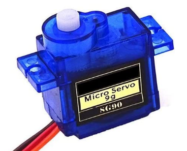
| 項目 | 仕様 |
| PWMサイクル | 20ms |
| 制御パルス | 0.5ms~2.4ms |
| 制御角 | ±約90°(180°) |
| 動作速度 | 0.1秒/60° |
| 動作電圧 | 4.8V(~5V) |
| 角度 | μs | Duty% | Duty Cycle ※ |
| -90 | 500 | 2.5 | 25.6 |
| -45 | 975 | 4.88 | 50.0 |
| 0 | 1450 | 7.25 | 74.2 |
| 45 | 1925 | 9.63 | 98.6 |
| 90 | 2400 | 12 | 122.9 |
※Duty Cycle = 100% のときに1024とした場合の値
import webiopi
import time
########################################################
# サーボ制御
########################################################
import wiringpi
def getServoDutyForWebIOPi(val):
val_min = 0.0
val_max = 1.0
servo_min = 25 # 50Hzで, 0.7ms
servo_max = 123 # 50Hzで, 2.0ms
duty = int((servo_max-servo_min)*(val-val_min)/(val_max-val_min) + servo_min)
return duty
wiringpi.wiringPiSetupGpio() # GPIO名で番号指定
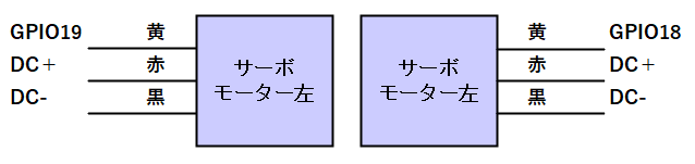
wiringpi.pinMode(18, wiringpi.GPIO.PWM_OUTPUT)
wiringpi.pinMode(19, wiringpi.GPIO.PWM_OUTPUT)
wiringpi.pwmSetMode(wiringpi.GPIO.PWM_MODE_MS) # 周波数固定
wiringpi.pwmSetClock(375) # 50 Hz
wiringpi.pwmWrite(18, getServoDutyForWebIOPi(0.5))
wiringpi.pwmWrite(19, getServoDutyForWebIOPi(0.5))
@webiopi.macro
def setHwPWM1(duty, commandID):
wiringpi.pwmWrite(18, getServoDutyForWebIOPi(float(duty)))
@webiopi.macro
def setHwPWM2(duty, commandID):
wiringpi.pwmWrite(19, getServoDutyForWebIOPi(float(duty)))
<!DOCTYPE html>
<html lang="ja">
<head>
<meta charset="UTF-8">
<title>RaspberryPi</title>
<meta name="viewport" content="width=device-width,initial-scale=1">
<script type="text/javascript" src="/webiopi.js"></script>
</head>
<body>
<H1 style="text-align:center;">RaspberryPi</H1>
<form name="form">
<table style="margin:0 auto;"><tr><td style="text-align:center;">
<table style="margin:0 auto;"><tr><td>
右<input type="range" name="range21" min="0" max="20" step="1" value="10" onchange="sv1(form.range21.value)"><br>
左<input type="range" name="range22" min="0" max="20" step="1" value="10" onchange="sv2(form.range22.value)"><br>
</td></tr></table>
</form>
<script>
//*******************************************
//サーボ用
//*******************************************
webiopi().ready( initialize_webiopi );
// 命令送信ごとに増加するIDを作成(iOSのSafariでPOSTがキャッシュされることの対策)
var commandID=0;
function initialize_webiopi(){
    // GPIOの状態を監視しない
//  webiopi().refreshGPIO(false);
}
function sv1(z) {
  ratio = z / 20 ;
  webiopi().callMacro("setHwPWM1", [ratio, commandID++]);
}
function sv2(z) {
  ratio = z / 20 ;
  ratio = 1.0 - ratio;
  webiopi().callMacro("setHwPWM2", [ratio, commandID++]);
}
</script>
</body>
</html>
120 万画素、ビデオ解像度(1280×720)、最大フレームレート30fps、内臓マイク付

次のコマンドでインストールします。
Webサーバーの起動(インプットをRaspberry Pi用に修正)コマンド。
下記のコマンドで開始します。画像サイズ、フレームレート(fps)は任意に設定してください。
/usr/local/bin/mjpg_streamer -i "input_raspicam.so -x 640 -y 480 -fps 15 -q 80"
-o "output_http.so -p 8080 -w /usr/local/share/mjpg-streamer/www"
Webサーバーを起動しています。
http://RaspberryPiのIPアドレス:8080/へアクセスするとサンプルスクリプトとストリーミングされた映像を見ることができます。
JavaScriptのサンプルスクリプトは必要に応じてストリーミングコンテンツの場所を変更します。
<!DOCTYPE html>
<html lang="ja">
<head>
<meta charset="UTF-8">
<title>RaspberryPi</title>
<meta name="viewport" content="width=device-width,initial-scale=1">
<script type="text/javascript" src="/webiopi.js"></script>
</head>
<body onload="createImageLayer();">
<H1 style="text-align:center;">RaspberryPi</H1>
<div id="webcam" style="text-align:center;">
<!--noscript--><img src="http://192.168.0.10:8080/?action=snapshot" /><!--/noscript-->
</div>
<script>
//*********************************************
// Webカメラ
//*********************************************
/* Copyright (C) 2007 Richard Atterer, richard息atterer.net
   This program is free software; you can redistribute it and/or modify it
   under the terms of the GNU General Public License, version 2. See the file
   COPYING for details. */
var imageNr = 0; // Serial number of current image
var finished = new Array(); // References to img objects which have finished downloading
var paused = false;

function createImageLayer() {
  var img = new Image();
  img.style.position = "absolute";
  img.style.zIndex = -1;
  img.onload = imageOnload;
  img.onclick = imageOnclick;
//img.src = "http://" + document.getElementById("ipa") + ":8080/?action=snapshot&n=" + (++imageNr);
  img.src = "http://192.168.0.10:8080/?action=snapshot&n=" + (++imageNr);
  var webcam = document.getElementById("webcam");
  webcam.insertBefore(img, webcam.firstChild);
}

// Two layers are always present (except at the very beginning), to avoid flicker
function imageOnload() {
  this.style.zIndex = imageNr; // Image finished, bring to front!
  while (1 < finished.length) {
    var del = finished.shift(); // Delete old image(s) from document
    del.parentNode.removeChild(del);
  }
  finished.push(this);
  if (!paused) createImageLayer();
}

function imageOnclick() { // Clicking on the image will pause the stream
  paused = !paused;
  if (!paused) createImageLayer();
}
</script>
</body>
</html>
下記のコマンドで開始します。画像サイズ、フレームレート(fps)は任意に設定してください。
$ /usr/local/bin/mjpg_streamer -i "input_uvc.so -r 320x240 -fps 15"
    -o "output_http.so -p 8080 -w /usr/local/share/mjpg-streamer/www"
自動起動設定をsystemd 「/etc/systemd/system/mjpg_streamer.service」ファイルに、下記の様に作成します。
# /etc/systemd/system/mjpg_streamer.service
    [Unit]
    Description=mjpg-streamer
    After=syslog.target

    [Service]
    Type=simple
    WorkingDirectory=/usr/local/bin/
    ExecStart=/usr/local/bin/mjpg_streamer -i "input_uvc.so -r 320x240
    -fps 15"
    -o "output_http.so -p 8080 -w /usr/local/share/mjpg-streamer/www"

    TimeoutStopSec=5
    StandardOutput=null

    [Install]
    WantedBy = multi-user.target
作成したファイルを読み込みます。
$ sudo systemctl daemon-reload
以下コマンドでサービスの自動起動を設定します。
$ sudo systemctl enable mjpg_streamer
自動起動を停止したい場合は以下のコマンド
$ sudo systemctl disable mjpg_streamer
サービスの起動と停止は以下のコマンド
$ sudo systemctl start mjpg_streamer $ sudo systemctl stop mjpg_streamer
サービスの自動起動を設定したら再起動して確認してください。